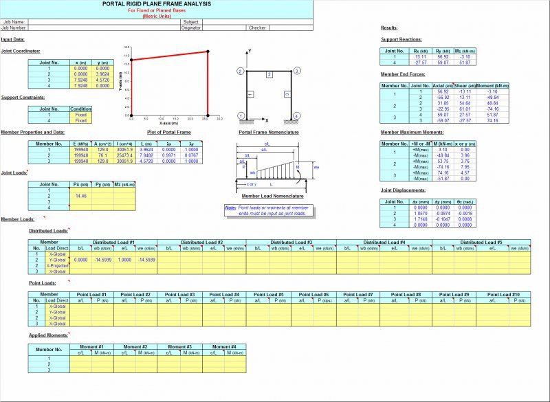
FRAME is a spreadsheet program written in MS-Excel for the purpose of plane frame analysis of portal and gable rigid plane frames subjected to various types of loading. Specifically, the "stiffness matrix" method of analysis is used to determine the unknown joint displacements, support reactions, and member end forces. Individual frame members are also analyzed to determine the shears and intermediate moments. Plots of both the shear and moment diagrams are also produced. Also, the frame is drawn for visual confimation of geometry/configuration.
Program Assumptions and Limitations:
1. This program uses the "stiffness matrix" method of analysis and four (4) following basic analysis assumptions:
- Members must be of constant cross section (E and I are constant for entire length).
- Deflections must not significantly alter the geometry of the problem.
- Stress must remain within the "elastic" region.
- Since this analysis is "first-order", the effects of "P-D", "P-d", and shear deformation are not included.
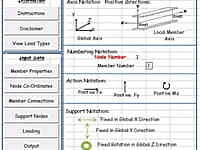
2. Additional assumptions and features are as follows:
- Frame support joints may each be either fixed or pinned.
- Frame support joints may be at different levels (elevations).
- Columns must be vertical (cannot be sloped).
- For a portal frame, the top (roof) member may be flat or sloped in either direction.
3. A vertical load, horizontal load, and externally moment may be applied to any of the joints of the frame. These joint loads are to be applied in "global" axes directions. Note: Joint loads applied directly at supports are merely added directly to support reactions and are not reflected in member end force values.
4. On any individual member, this program will handle up to five (5) full uniform, partial uniform, triangular, or trapezoidal loads, up to ten (10) point loads, and up to four (4) externally applied moments. For vertical members, distributed loads and point loads are input in a "X-Global" sence of direction. For flat or sloped top (roof) members, distributed loads may be applied global over actual member length or applied global over the "projected" member length. Program designations are "Y-Global", "Y-Projected", "X-Global", and "X-Projected".For a flat top (roof) member of a portal frame, "Y-Global" and "Y-Projected" loads produce the same results.Uniformly distributed gravity (dead or live) load would be an example of a "Y-Global" distributed load on a sloped top (roof) member, while lateral uniformly distributed wind load on sloped top (roof) member would be an example of an "X-Projected" distributed load. A uniformly distributed load such as wind suction perpendicular (normal) to a sloped top (roof) member must be resolved into Y-Global and X-Global component values by user.
5. This program will calculate the member end reactions, the member end forces (axial, shear, and moment), the member maximum positive and negative moments (if applicable), and the joint displacements. The calculated values for the maximum moments are determined from dividing the member into fifty (50) equal segments with fifty-one (51) points, and including all of the point load and applied moment locations as well. (Note: the actual point of maximum moment occurs where the shear = 0, or passes through zero.)
6. The user is also given the ability to select an AISC W, S, C, MC, or HSS (rectangular tube) shape to aide in obtaining the required moment of inertia for input. (This facility is located off to the right of the main page.)
7. This program contains numerous “comment boxes” which contain a wide variety of information including explanations of input or output items, equations used, data tables, etc. (Note: presence of a “comment box” is denoted by a “red triangle” in the upper right-hand corner of a cell. Merely move the mouse pointer to the desired cell to view the contents of that particular "comment box".)
* FRAME download link provides freeware version of the software.
Bending Moments, Axial and Shears Forces in a Plane Frame
A Plane Frame Analysis for bending moments, axial and shears forces in a plane frame structure under point loads, UDL's, linearly varying distributed loads (soil pressures) and moments.
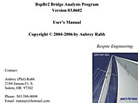
Plane Frame Structural Analysis For Bridge Engineers
RspBr2 is a plane frame structural analysis program to aid bridge engineers in design and checking beam bridges.
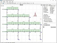
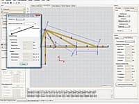
Structural Analysis of Plane (2D) frames
EngiLab Frame. 2D is an easy-to-use yet powerful engineering tool for the structural analysis of plane (2D) frames for Windows, using a 3-DOFs (Degrees of Freedom) per node approach.
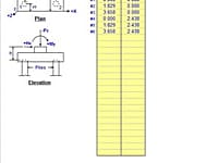
Pile Group Analysis for a Rigid Pile Cap/Mat
PILEGRP is a spreadsheet program written in MS-Excel for the purpose of analysis of pile groups with rigid caps using the elastic method.
2D Frame Analysis is a powerfull application which uses optimized finite elements (beam elements) in order to perform static analysis of beams, frames and trusses.
Submit a review about FRAME software with your social media profile
No comments yet. Be the first to comment.